BUILD TUNE RACE RC YACHTS

Components for the bow, stern and bulkhead, simply a glass and epoxy sheet laid on a flat board covered in packaging tape which is a great release agent. For the rudder and servo supports, I laid glass over strip wood wrapped in packaging tape to create a light rigid beam to bond across the boat.

The hull is laid up in the same way as the plug. Pre cut the cloth and mark a centreline on the hull and the cloth. Allow for an overlap of 1 inch on the foredeck.

I used West systems slow cure epoxy resin which in the Summer gave me about half an hours work time. Stop work when the epoxy starts to go stringy and clean your tools with Acetone before mixing a fresh pot of epoxy.
I use Nitril gloves which I wash in acetone to remove any sticky epoxy. I also use a full face filter mask although this is not needed. Unlike Polyurethane, epoxy does not smell too bad
To begin the layup, paint the hull with epoxy.
Add the first layer of E cloth and saturate the glass with epoxy using the aluminium roller. Take your time and make sure you get rid of all air bubbles. I worked on the hull first and then turned the mould over to work on the deck. Allow a 1 inch overlap on the deck and cut any excess cloth away with scissors. Keep a jar of acetone handy to keep the scissors clean.
I added more epoxy over the first layer of E cloth prior to adding the second layer. Roll out and finish as per the first layer. Repeat for the final layer of S cloth
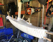
Wrap the finished hull tightly in Peel ply.
When I built the hull in about 75 degrees, I had to mix a second lot of epoxy for the final layer of S cloth as the first lot started curing.
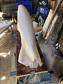
Once hardened, remove the peel ply, then add 2 coats of high build epoxy primer. Like the plug the hull will look a mess but will look great once sanded.
Sand the hull so you can see through to glass but do not cut any fibres. This will make the hull as light as possible and ready for a top coat of 2 pack polythene which is done after fit out. Fix any faults/holes as necessary.
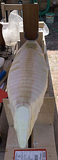
Once happy with hull finish cut through the centreline of the the foredeck and stern deck. Brad suggested a knife but I used a fine cutter on a Dremel. Prise the hull off the mould. This process was much easier than I thought it would be. The whole structure is flexible so once off the mould so put in a jig to keep the designed shape.


Finisci il ponte principale
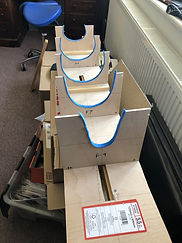
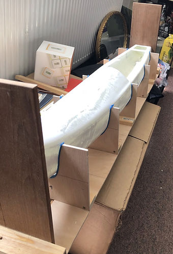
Non appena lo scafo è fuori dallo stampo mettilo dritto in una maschera per sostenere lo scafo. Ho ritagliato dei telai in compensato usando i piani e li ho fissati ad una robusta tavola piana La dima servirà per allineare la pinna e il timone
Fare clic su qualsiasi immagine per espandere l'immagine.
Bond the foredeck and stern deck

What you need
-
5 minute epoxy
-
Slow cure epoxy
-
Bent piece of wire as long as the foredeck
-
1" glass tape
-
Bow and stern plates
The process
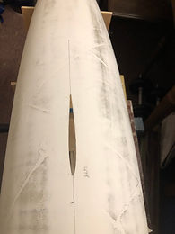
Tape the the top of the previously cut foredeck and stern together with masking tape prior to bonding below.
Sand the underside of the foredeck to provide a key for the 1"tape you are about to apply
Bond the underneath of cut foredeck and stern deck with 1" fibreglass tape.

Allow to cure and remove the masking tape. I put the glass tape underneath the deck and on top but I think you only need to bond underneath and fill the gap on top.
To get the tape all the way up the foredeck, wet the tape with epoxy and roll up. Using the wire with a 1" bend at the end, to support the roll and unroll it right (with the hull upside down) to the end of the foredeck. Once unrolled it should sit flat and use the wire to move the tape if necessary. See image 4.
Remember to put some peel ply over the top of the tape on top of the deck. Image 6. (This was probably an unnecessary step as I think the tape only needs to go on the underside.)
The foredeck will be very strong because you will have 6 layers of glass including the overlay and the 1" tape. Slightly over engineered I think.
Repeat the process on the stern deck. I had to put a plate across the stern and the next bridge as I had not finished the original layup properly. Image 8 and 9.


Having taped on top of the foredeck I had to re apply 2 coats of high build epoxy and sand down. There is no need to do this if you bond underneath the deck only.
I fitted 2 perpendicular end plates onto the jig so I could shape the bow and stern on the hull to be, one, vertical and two, at 90 degrees to the centre line of the boat. Image 10

Trim the bow and stern plate and fit with 5 min epoxy. Spot glue in place initially and then seal and fillet with epoxy and micro balloons.
Lega il ponte di prua e il ponte di poppa
Quello di cui hai bisogno
Resina epossidica 5 minuti
Resina epossidica a polimerizzazione lenta
Pezzo di filo piegato lungo quanto il ponte di prua
Nastro di vetro da 1"
Piastre di prua e di poppa
Il processo
Fissare con nastro adesivo la parte superiore del ponte di prua e della poppa precedentemente tagliati prima dell'incollaggio sottostante. Vedi immagine 5.
Carteggiare la parte inferiore del ponte di prua per fornire una chiave per il nastro da 1" che si sta per applicare
Fissare la parte inferiore del ponte di prua e di poppa tagliati con nastro in fibra di vetro da 1". Immagine 4. Lasciare polimerizzare e rimuovere il nastro adesivo. Ho messo il nastro di vetro sotto il ponte e sopra, ma penso che tu debba solo incollare sotto e riempire il vuoto sopra.
Per ottenere il nastro fino al ponte di prua, bagnare il nastro con resina epossidica e arrotolare. Usando il cavo con una curva di 1" all'estremità, puoi sostenere il rotolo e srotolarlo fino all'estremità del ponte di prua (con lo scafo capovolto). Una volta srotolato, dovrebbe rimanere piatto e utilizzare il filo per spostare il nastro, se necessario. Vedi immagine 4.
Ricordati di mettere un po' di peel ply sulla parte superiore del nastro in cima al ponte. Immagine 6. (Questo è stato probabilmente un passaggio non necessario poiché penso che il nastro debba solo andare sul lato inferiore.)
Il ponte di prua sarà molto resistente perché avrai 6 strati di vetro compreso il rivestimento e il nastro da 1". Leggermente troppo ingegnerizzato.
Ripetere il processo sul ponte di poppa. Ho dovuto mettere una lastra a poppa e al ponte successivo perché non avevo finito bene il layup originale. Immagine 8 e 9.
Avendo registrato sopra il ponte di prua, ho dovuto applicare nuovamente 2 mani di resina epossidica ad alto spessore e carteggiare. Non è necessario farlo se ti leghi solo sotto il ponte.
Ho montato 2 piastre terminali perpendicolari sulla maschera in modo da poter modellare la prua e la poppa sullo scafo in modo che fossero, una, verticale e due, a 90 gradi rispetto alla linea centrale della barca. Immagine 10
Tagliare la prua e la piastra di poppa e montare con resina epossidica 5 min. Inizialmente incollare la colla, quindi sigillare e filettare con resina epossidica e micro palloncini. La figura 8 mostra l'adattamento iniziale.
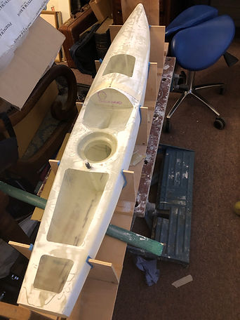
Infine rimuovere il ponte in eccesso in modo che i fori siano visibili secondo il piano. Vedi immagine 7 e 8.
Nell'immagine 5 è presente solo il ponte di poppa. Sulla prossima barca completerò il ponte fino al palo della spina.
ora arriva quella che penso sia la parte più difficile del processo di costruzione. Marcatura su e tagliando un foro nello scafo per la pinna e incollando in una cassa della pinna allineata e incollandola alla coperta e alla paratia di prua. Quando costruirò la mia prossima barca aggiungerò le foto del posizionamento delle pinne.
Fare clic su qualsiasi immagine per espandere l'immagine.
The fin case, bulkhead and forward aft deck
What you need
-
5 minute epoxy
-
Slow cure epoxy
-
Fin
-
Fin case
-
Rudder
-
Rudder stock brass tubes
-
Cross bars for rudder stock and rudder servo mount.
-
Prepared forward part of the aft deck
-
Cut out bulkhead shape to fit under fordeck
-
1"glass tape
-
Various fittings, jib tack bolts, mast ram, mainsheet post, back stay bolt, mainsheet pulley blocks, fairleads to allow the endless mainsheet to go through bulkhead
The Details
Tape the hull into the jig so the shroud points on the deck are parallel to the base of the jig. Everything will be aligned to this.
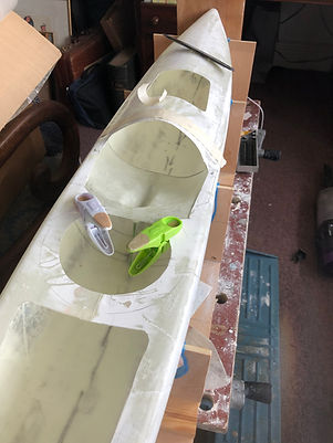
Measuring from the stern datum, mark the front and back of the fin hole on the outside of the hull. Then mark a centreline which you will have marked on the frames of the jig. This will get the correct alignment for the fin hole. Remove the hull and using the fin, mark the contour of the fin. Cut out the slot for the fin using a Dremel or similar being careful to cut well inside the line. Use sandpaper to open the slot to fit the fin exactly.
Tape the hull back in the jig. With the fin in the slot, push the fin case over the fin so that the bottom of the case is lying on the hull.
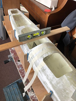
There are two measurements on the plan to align the fin, one shows the tip of the fin where is enters the bulb. This should be 330mm from the bottom of the hull and the other measures from the same fin tip to the bottom of the bow of the boat. If set up correctly the leading edge of the fin should be perpendicular to the waterline. Shape the bottom of the fin box and fin until this is achieved. Ideally the fin should fit all the way into the fin box.
I used some string to determined the position of the tip of the fin.

Reinforce the shroud bolt locations with half an inch of 1" tape and once dry fit the shrouds.
There is a huge amount of strength with this design in this area and no further reinforcement is needed.
Fit the shroud bolt now while you have access to the underside of the deck.
Once the base of the fin box is shaped and the fin aligned, now is the time to dry fit the forward part of the aft deck and trim the top of the fin box until the deck fits snuggly. Spot glue the fin box in place with the fin in the box and support in the right position.

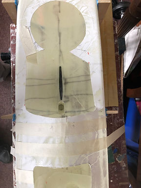
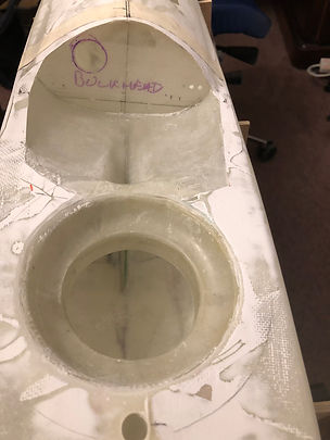
Once fixed seal the fin box to the hull with 5 min epoxy and microballoons with a small fillet. Finally reinforce the fin box to the hull with 1"glass tape and epoxy.

With the fin box in place, dry fit the forward part of the deck with the fin box and forward bulkhead.
Once happy with fit, do a final check that the forward bulkhead is in the right place from the stern datum. Get this wrong and you will have issues with your mast ram. Spot glue with 5 min epoxy and micro balloon. With 5 min epoxy and micro balloon seal the bulkhead and seal where the fin box connects with the deck. Finally reinforce the top of the fin box with fin one inch tape.

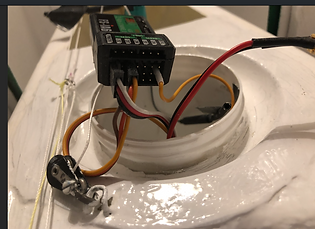
Finally glue the radio pot holder under the deck and seal with epoxy. In my first build I glued the pot on top which looks messy.

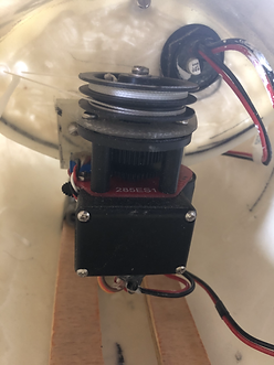
Bond in the cross beams for the servo and rudder stock with one inch tape See image below for positions. Remember to sand the inside of the hull to create a good keyed surface.
Drill the hole in the deck for the fin bolt and mast. Now is the time to check for leaks. Fill the depressed area of the deck forward of the radio pot with water and see if there are any leaks.
Drill a 4mm hole in the hull for the rudder, with the central point located from the jig and distance from the aft datum measured off the plan.
The rudder stock is 2 tubes of brass, one 5mm o/d and one 4mm o/d. The two tubes slot into one another and the rudder post goes inside for a very tight fit.
Mark on the rudder brace bar a line which when a hole is drilled for the stock ensures the trailing edge of the rudder does not extend beyond the stern of the boat. The rudder stock will project a couple of mm above the cross bar. Drill a hole in the centre and ream it wide perpendicular to the hull. Fit the stock in place on the rudder and in the boat. Apply some 5 min epoxy with micro balloon to fix the top of the stock with the rudder exactly aligned with the keel. Leave to set, then seal the stock in the hull and reinforce the top if necessary. The worst is over. My first cross beam was so strong I saved weight by cutting it in half. The next cross beam will be much lighter.
Paint the whole boat in 2 pack polyurethane top coat and lightly rub and t-cut to desired finish


Fit the mainsheet post, backstay bolt, aft pulley for mainsheet, fairleads for sheet control through the bulkhead, setting these as low as possible so they don't interfere with the kicker on a run on port gybe. Fit the 4 jib sheet leads in the foredeck and the 3 tack bolts. Finally, drill a bung hole, push a needle through the centre of the bung, thread a chord and tie to the backstay.

Drill two bolts to hold the winch bracket in the forward bulkhead. Align the winch with the fairleads.
The bracket was just a 90 degree moulding cut to shape around the winch and enough flange to brace it securely to the bulkhead.

Drill a hole for the mast ram and fit.
Bond a strengthening post in the foredeck around the jib tack area to stop foredeck lifting under load.

Don't fit the radio pot until correctors have been fitted.
L'ultimo lavoro di montaggio sulla barca
Quello di cui hai bisogno
Timone per timone
Connettore dal timone al servo
Servo
Ricevitore
Batteria LiFeP04 batteria 1600mA (più di un intero giorno di vita). Potresti usare un minimo di 900 mA se hai bisogno di risparmiare peso.
Interruttore on/off impermeabile
Verricello RG e staffa di supporto.
Il processo
Praticare un foro nella paratia anteriore sul lato sinistro per l'interruttore di accensione/spegnimento elettrico e montare.
Montare il verricello sulla staffa di supporto e montare liberamente sulla paratia.
Praticare un foro nella staffa trasversale per il servo e montare e far passare il cavo al piatto della radio.
Fai un foro nella parte superiore del piatto della radio appena sotto il suo telaio di supporto e fai passare il cavo del servo e dell'interruttore per la batteria all'interno del piatto attraverso il foro.
Collegare il servo del timone al canale 1 del ricevitore.
Collegare il connettore del verricello al canale 3 e inserire il terzo cavo del verricello allentato su un pin centrale ridondante, ad esempio il canale 5.
Collegare l'interruttore al verricello. Usa i connettori XT30 dove possibile o otterrai abbastanza potenza per il verricello.
Se accendi l'alimentazione, con un po' di fortuna un trasmettitore acceso sposterà il timone e il verricello.
C'è un'intera sezione sulla configurazione del trasmettitore radio QUI .
Se tutto funziona, sei pronto per montare il regolatore continuo del foglio.
Il foglio infinito è un lavoro complicato. Ho acquistato il verricello con una puleggia di ritorno autotensionante, cioè è dotato di una molla che impedisce l'allentamento della linea di scotta.
Trova i punti finali del verricello spostando completamente su e giù lo stick di controllo sul trasmettitore. Uso su per il foglio completamente fuori e giù per completamente dentro.
Lasciare lo stick di controllo verso il basso (foglio dentro). Prendi due cime e passa attraverso i passacavi della paratia e corri verso il verricello. La linea esterna tirerà i fogli e l'interno farà uscire il foglio. Sul verricello la puleggia inferiore è scottata, la puleggia sospesa superiore è scottata. Con la linea esterna, lega la puleggia inferiore e avvolgi 5 volte la puleggia. Lega la linea interna alla puleggia superiore ma usa solo una e una mezzo giro. Mantenendo le linee leggermente tese in modo da non perdere gli avvolgimenti sul verricello, ora puoi montare saldamente il verricello.
La linea esterna viene fatta scorrere lungo il ponte e attraverso la puleggia di poppa vicino al paterazzo sul lato di dritta, infilata all'interno e quindi legata a un anello inossidabile da 5 mm a 2 "dal blocco della puleggia. La linea interna (foglio esterno) può essere tesa, sentirai la resistenza della puleggia autotensionante e si legherà all'anello inossidabile in modo che il sistema infinito sia ragionevolmente stretto. Le scotte della randa e del fiocco si legheranno all'anello. Il sistema di scotta randa infinito è completo.


If you turn the power on, with any luck a switched on transmitter will move the rudder and winch.
There is a whole section on the setup of the radio transmitter HERE.
If all works you are ready to fit the endless sheet adjuster.
The endless sheet is a fiddly job. I bought the winch with a self tensioning return pulley, i.e it is fitted with a spring that will stop the sheet line going slack.
Find the end points of the winch by moving the control stick on the transmitter fully up and down. I use up for sheet fully out and down for fully in.
Leave the control stick down (sheet in). Take two lines and thread through the bulkhead fairleads and run to the winch. The outer line will pull the sheets in and the inner will let the sheet out. On the winch the bottom pulley is sheet in, the top sprung pulley is sheet out. With the outer line, tie off on the lower pulley and wrap 5 times round the pulley. Tie the inner line to the upper pulley but only use one and a half turns. Keeping the lines lightly tensioned so you don't lose wraps on the winch, you can now securely mount the winch.
The outer line is run along the deck and through the aft pulley near the backstay on the starboard side, threaded out to in and then tied to a 5mm stainless ring 2" from the pulley block. The inside line (sheet out) can be tensioned, you will feel the resistance of the self tensioning pulley and tie off to the stainless ring so the endless system is reasonable tight. The main and jib sheets will tie off to the ring. The endless mainsheet system is complete.


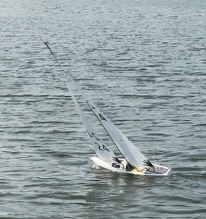
Il risultato finale
Next Section